Description
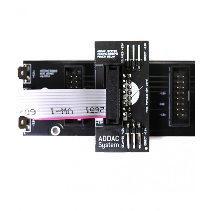
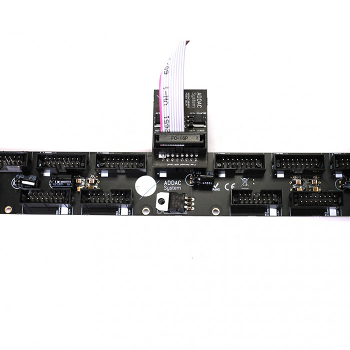
These small boards are designed to bring some extra flexibility and customisation when powering up a modular system. There are 2 models – ADDAC901PDO for Old style Busboards and ADDAC901PDN for New style Busboards.
Whenever a modular system is turned on there’s a current spike upon startup that will momentarily influence the PSU output, and it can take up to a couple seconds for the PSU to stabilize to its stated specifications. PSUs can also have some delay between their power lines where one polarity is provided prior to the second one. They also commonly have a ramp like startup. All this behaviour is common and normally not a problem. While most modules are fine with this situation, there are others that can suffer from this and in a worst case scenario won’t startup correctly. Some modules can also be sensitive to the timing of the ±12v, some may require both to arrive at the same time others won’t start if -12v arrives prior to the +12v, etc.
These power delay boards allow you to time the deployment of power to a specific module in your Eurorack case. They can delay each power line independently by up to 3 seconds, meaning that after powering up your modular it will wait for 3 seconds until it will provide power to the specific module connected to it. This delay time can also be customized by A DIY user by replacing a couple capacitors.
Using this small board with more sensitive modules allow them to power up at a time past the initial spike and where the PSU is already stable and it will guarantee that the ±12V is delivered at exactly the same time.
Besides this very technical use there are other creative and useful uses, for example plug it to those specific modules that “drive” your patch, like a sequencer or a clock and have them power up later so that other modules have time to start up and stabilize before starting up the clock. Go even deeper in this idea and have different 900PDs with different capacitors that will allow you to “program” a sequential module power up, useful for generative patches that run on a power timer in exhibitions and galleries.
One more useful hack is to use it in those cases where your frame won’t power up due to the initial current “spike”, which sends it over its limits and trips the protection mechanism. The usual “hack” is to unplug one or two modules allowing it to power up and then connect the extra modules in. ***Warning*** power up issues like these simply means your PSU is close to its maximum and the PCB shouldn’t be used as a permanent fix and we advise upgrading the PSU. However it will make it easier in that situation where you add one last minute module for that gig in a few hours and that extra module trips the PSU protection, then as a temporary hack the PCB will make it easier for the frame to power up at the gig.
There are 2 sets of jumpers to independently set the power line to be delayed, -12V, +12V or both. This PCB will be plugged onto your busboard and, in turn, allow a ribbon power cable to be connected to it.
DISCLAIMER: Both the ADDAC901PDO and the ADDAC901PDN are not to be used with modules that require external +5V supply.