Description
These have a Matt Black soldermask finish with yellow text and Gold ENIG plating. Unlike other suppliers these have the bevelling of the card edge and with full spec ‘Gold Fingers’ plating for longevity. These cards are the required 1.6mm thickness to mate correctly with the 208 edge connector.
Bevelled card connector edge: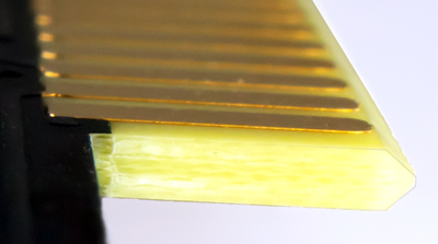
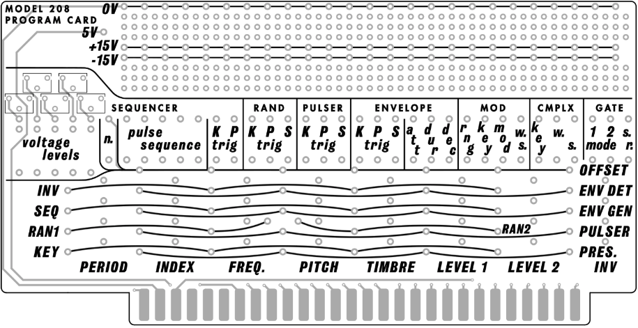
These Model 208 Program Cards are designed to interface with the “PROGRAM BOARD” edge connector of a Buchla & Associates Model 208 Stored Program Sound Source module and its reissues / compatible units. This is the version with the prototyping area where additional active circuitry can be added if desired. For guidance on general use, see Allen Strange’s “Programming and Meta-Programming the Electro Organism” manual.
PLEASE NOTE:
**Inserting / removing program cards whilst the 208 is powered is not recommended or supported**
**The system power rails are exposed in the prototype area – use with caution to avoid damage to the power supply or 208 module**
**Not all functions provided on the cards are available on all 208 type modules**
**These cards are not compatible with Roman Filippov’s 208r rev 1**
Beyond the settings / connections available on the original cards, the following features are provided:
- A label area on the rear of the card for easy identification of presets.
- Modulation oscillator range switch setting (where this is available on the 208 edge connector).
- An extra connection point for each of the random voltage outputs.
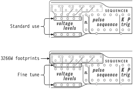
- Footprints for optional multi-turn trimmer potentiometers (Bourns 3266W type) in series with the sequencer voltage level settings for fine tune when programming pitched sequences. Depending on whether a trimmer will be fitted, solder fixed resistors between the pads indicated:
As the relationship between the value of resistor required and front panel setting is non linear, different value trimmers will be required depending on the desired range. A suggested approach is to take the fixed value resistor indicated for the approximate value, select a trimmer approximately 10% to 20% of this value, and reduce the value of the fixed resistor by 5% to 10% – for example for a front panel value of 4, a 300kΩ resistor would be used – this could be substituted by a 270kΩ resistor and 50kΩ trimmer to provide a reasonable range of adjustment around this value. Alternatively for a wide range of adjustment a fixed value of 120kΩ can be used with a 1MΩ trimmer, however the resolution of adjustment will be coarser at the top end than at the bottom.
- 5V rail brought out to the prototyping area (where this is available on the 208 edge connector), for easier application of microprocessors and logic in any additional circuitry.
DOCUMENTATION
Product Information Document – Programming Guide
This PCB is an ‘open source’ type of project and is licensed under the GNU General Public License v3.0